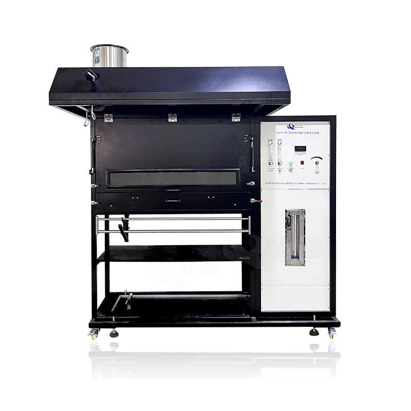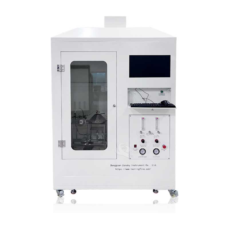
The Building Material Ignitability Fire Tester Comply with the standard requirements of ISO5657-1997 "Reaction to fire tests—Ignitability of building products using a radiant heat source"
1. Scope of application:
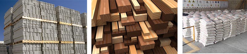
It is suitable for the ignitability test of the fire surface when the material, composite material or component with a thickness of not more than 70mm is placed horizontally under the specified heat radiation conditions. It can be used to evaluate wall and ceiling lining materials, floorings systems, exterior cladding and air heat pipe insulation, etc. In a specific fire scene, the fire situation of the product can be accurately described, so the test results can reflect the combustion performance of the product in actual use. Through the test, it can be used to distinguish which materials are easy to ignite and which materials are not easy to ignite, which is helpful for differentiate the fire hazard of materials.
2. Compliant standards:
Comply with GB/T14523-2007 "Reaction to fire tests—Ignitability of building products using a radiant heat source"
Comply with the standard requirements of ISO5657-1997 "Reaction to fire tests—Ignitability of building products using a radiant heat source"
3. Main performance parameters:
3.1 Whole machine: It consists of radiation cone, ignition device, nozzle, pressing plate mechanism and supporting frame, temperature recorder, gas system, signal acquisition and processing, computer, oven, etc.
3.2 Specimen support frame, guard plate and pressure plate:
3.2.1 The sample support frame and other parts of the fixture are made of stainless steel. The support frame is made of square steel pipes with a wall thickness of 1.5mm and a size of 25mm × 25mm, with a total size of 275mm × 230mm.
3.2.1 The side length of the horizontal guard plate is 220mm and the thickness is 4mm. The horizontal shield is fixed 260mm directly above the base frame by 4 feet with a diameter of 16mm installed on the corners of the shield. A circular opening with a diameter of 150mm is cut in the center of the guard plate, and the upper edge of the opening is cut into a chamfer of 45° with the horizontal plane and a width of 4mm.
3.2.3 Two steel vertical guide rods with a length of less than 355mm and a diameter of 20mm are installed on the frame, which are respectively installed at the midpoint of each short side of the support frame. Below the guard plate, a 25mm×25mm horizontal adjustment rod is installed between the two vertical guide rods. The adjusting rod can be slid on the guide rod or manually screwed to a certain position with screws. There is a vertical hole sleeve in the center of the adjusting rod, which is used to fix the vertical sliding rod with a diameter of 12mm and a length of 148mm. The top of the sliding rod is against the edge A square plate with a length of 180mm and a thickness of 4mm. The pressure plate pushes the lower bottom surface of the guard plate through the balance rotating arm, and the balance rotating arm is installed under the horizontal adjusting rod and bears against the bottom end of the vertical sliding rod.
3.2.4 There is a roller at one end of the swivel arm, which is placed on the wheel hub at the lower end of the vertical sliding rod, and an adjustment counterweight is installed at the other end. The counterweight can balance samples of different masses, and can apply a constant pressure of 20N between the sample and the guard plate. During the test, since the specimen may collapse, soften and melt, an adjustment and positioning device is provided to limit the upward movement of the pressure plate. The maximum distance is 5mm. A spacer can be selected between the pressure plate and the guard plate.
3.3 Radiation cones
3.3.1 Radiation cone: Rated power 3kw, radiation intensity: 10kW/m²~70kW/m² heating element, the heating element is a stainless steel electric heating pipe with a length of 3500mm and a diameter of 8.5mm, which is wound into a truncated cone and installed in a protective shield. inside the housing. The overall height of the cover is (75±1) mm, the top inner diameter is (66±1) mm, and the bottom inner diameter is (200±3) mm. The protective cover is made of stainless steel with a thickness of 1mm inside and outside, and a ceramic fiber insulation material with a thickness of 10mm and a nominal density of 100kg/M² is sandwiched in the middle. The heating element is firmly fixed on the inner surface of the shield by steel needles, and four clamps are used to fix and clamp the circumference of the shield at equal distances to prevent accidental relaxation of the electric heating tube at the bottom of the shield. For vertical projection, the wound heating element shall not cover more than 10% of the opening area at the top of the shield.
3.3.2 At the center of the opening of the guard plate or on the reference plane that coincides with the bottom surface of the guard plate, the radiation cone can generate irradiance of 10Kw/m²~70kW/m².
3.3.3 On the reference plane, the irradiance distribution provided by the radiation cone satisfies that the deviation between the irradiance and the central irradiance in a circle with an inner diameter of 50mm in the opening of the guard plate does not exceed ±3%; The deviation of the central irradiance shall not exceed ±5%.
3.3.4 The radiation cone is fixed on the lifting guide rod on the sample support frame through the fixture, and the lower edge of the radiation cone shield is fixed at (22 ± 1) mm above the surface of the shield.
3.3.5 Thermocouple: It is the K-type armored thermocouple and the reading of the thermocouple (main thermocouple) in close contact with the heating tube to control the heating temperature of the radiation cone. It is installed and fixed in a position opposite to the diameter of the main thermocouple. Each thermocouple was attached to a crimped heating tube and placed within 1/3 to 1/2 of the height of the radiant cone below the top surface, with one end of the thermocouple 8mm in an area of approximately the same temperature.
3.4 Ignition mechanism:
3.4.1 Ignition mechanism: it consists of ignition arm, secondary ignition source and cam.
3.4.2 The pilot flame is ejected from a nozzle made of stainless steel and installed at the end of the pilot tube.
3.4.3 The pilot flame is placed above the radiation cone, and the flue gas plume and decomposition products emerge from the top surface of the radiation cone. When placed in this position, the pilot flame nozzle is close to a secondary ignition source with a heat output not greater than 50W, which is capable of and repeatedly igniting the pilot flame. The propane flame is sprayed from a nozzle with an inner diameter of 1mm to 2mm, the flame length is 15mm, and the heat output is about 50W.
3.4.4 The pilot flame is located above the center point of the opening of the guard plate, the flame can be sprayed horizontally, and is perpendicular to the movement direction of the ignition arm, and the center of the nozzle hole is (10mm±)mm above the guard plate.
3.4.5 The ignition mechanism is provided with a limit cam and a drive cam, which can fix the lowest point of the ignition flame at any position between 20mm above the test position and 60mm below the test position during operation.
3.4.6 Ignition device: automatic electronic ignition for high voltage. Automatically move to the test position and automatically return.
3.4.7 Drive mode: It is driven by stepper motor and German Flender ball screw.
3.5 Specimen cover plate
3.5.1 Sample cover plate: automatic opening and closing. The opening and closing are automatically completed by the signal given by the computer.
3.5.2 The cover plate is made of USU304 stainless steel with a thickness of 2mm, which can cover the guard plate, and is equipped with a limit device to avoid hitting the guard plate, and a handle is added for easy removal.
3.6 Temperature monitoring system
3.6.1 The temperature controller of the radiation cone: adopts the temperature module, PLC program and PID control, and adopts the well-known brands of Taiwan Advantech and Japan's Mitsubishi.
3.6.2 Temperature control: Adopt Taiwan famous brand silicon controlled rectifier (SCR) to control the output, so that the maximum output value is not less than 15A current. The temperature resolution of the control heater is ±1℃, and the temperature range is 0℃~1000℃.
3.7 Radiometer (heat flux meter)
3.7.1 Radiometer: Gardon type, Hukseflux in the Netherlands, with a test range of 0kW/m2 to 100kW/m².
3.7.2 The radiometer accuracy is ±3%, repeatability: 0.5%, resolution: 0.1 kW/m2.
3.7.3 Voltage test device: The high-precision voltage signal amplifier is used to match the output of the radiometer, and its full-scale deviation, sensitivity and accuracy can enable the display resolution of the radiometer's irradiance to reach 0.1 kW/m².
3.8 Timer: resolution 0.01S, precision 1s/h.
3.9 Air propane supply system: Air and propane are supplied to the pilot flame through the regulating valve, filter, flow meter, and check valve flame extractor.
3.9.1 Gas regulating valve: adjust the pressure and flow of propane air supplied for ignition. The propane can be adjusted to 19mL/min ~ 20mL/min, and the air flow rate can be adjusted to 160mL/min ~ 180mL/min.
3.9.2 Filter: Eliminate the influence of impurities (such as oil droplets) entrained in the gas path on the flowmeter reading.
3.9.3 Flowmeter: can test the flow of propane and air supplied to the pilot flame with an accuracy of 3%.
3.10 Balance: weighing 5000g, indication accuracy 0.1g.
3.11 Control part: PLC programming, man-machine interface and computer control are adopted. The software adopts LabeView, a special development software for instruments and equipment, and a data acquisition control card; the test data can be viewed in real time during the control test process, and automatic data acquisition and processing, data storage and output of measurement results can be realized.
 WhatsApp:
 Mobile Phone:
 Contact Now