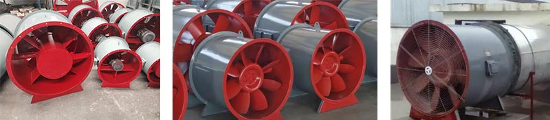
High temperature resistance test of fire-fighting smoke exhaust ventilator: It is suitable for axial flow (corresponding centrifugal type) fire-fighting smoke exhaust ventilator of machine number N0.3 to N0.18 to carry out high temperature resistance test in the laboratory;
1. Fire Resistance Test Furnace Scope of application:
1.1 High temperature resistance test of fire-fighting smoke exhaust ventilator: It is suitable for axial flow (corresponding centrifugal type) fire-fighting smoke exhaust ventilator of machine number N0.3 to N0.18 to carry out high temperature resistance test in the laboratory; as follows
2. Fire Resistance Test Furnace Compliant standards:
2.1 Comply with the GB/T9978.1-2008 test standard "Fire-resistance tests—Elements of building contruction—Part 1: General requirements" test standard;
2.2 Comply with the test standard of GA 211-2009 "High Temperature-Resistant Test Methods for Smoke And Heat Exhaust Ventilators";
2.3 Comply with the test standard of GB/T 1236-2000 "Industrial Fans - Performance Testing Using Standardized Airways";
2.4 Comply with the standard requirements of GB/T17428-2009 "Fire resistance test methods for ventilation ducts".
3. Fire Resistance Test Furnace Main technical parameters:
3.1 Instrument composition: fire resistance test vertical furnace, combustion control part, decompression system, pressure release and pressure measurement system, flue gas emission system, computer control system, four sets of sample test racks, gas flow measurement system, temperature measurement system (furnace temperature Data acquisition system, test component temperature acquisition system) and special test software.
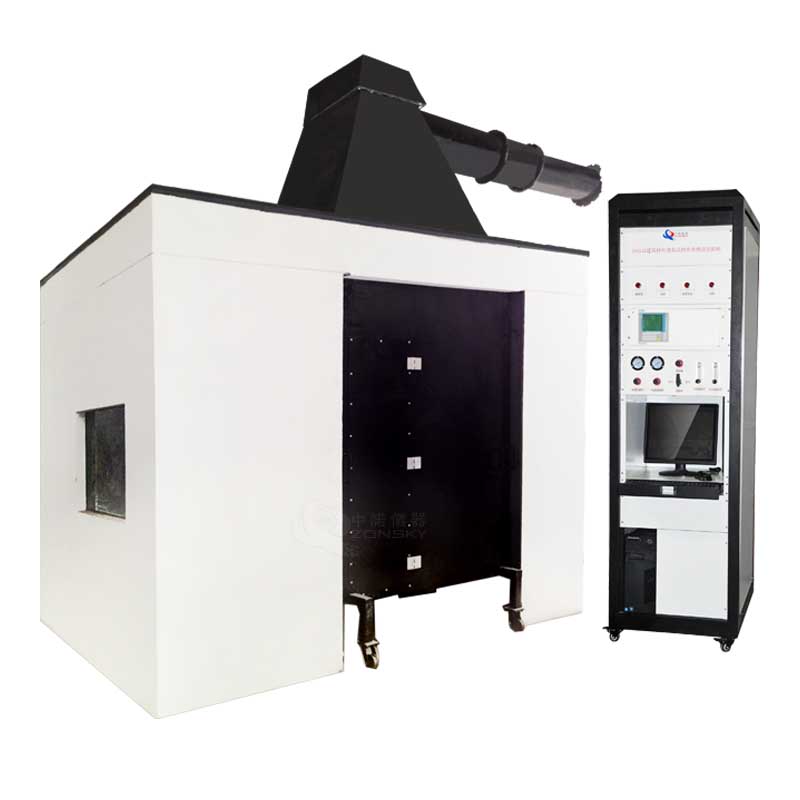
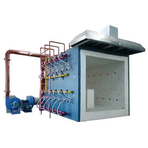
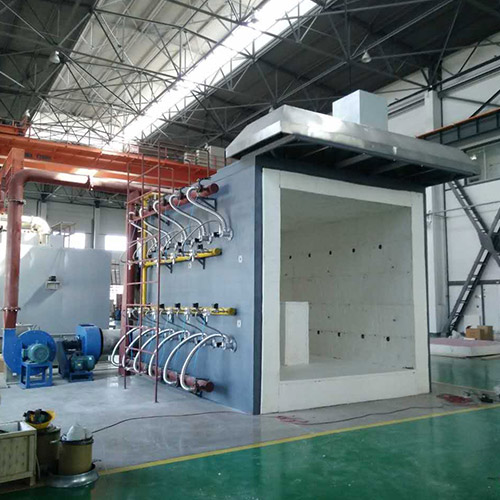
3.2 Test furnace: It is a vertical vertical test furnace, and the size of the furnace is 3.0M (length) x 4.5M (depth) x 3.0M (height).
3.3 Furnace body structure: see Figure 7. Five-layer structure is adopted. When the inner temperature is 1300°, the outer layer temperature is normal temperature. From outside to inside, they are: the first layer is a steel structure frame; the second layer is made of red bricks to form the periphery; the third layer is refractory high temperature asbestos; the fourth layer is refractory bricks; the fifth layer is mullite refractory high temperature cotton, The refractory temperature reaches 1600°C. When the temperature in the furnace reaches 1300°C, the temperature outside the furnace is room temperature. The service life is long, and the insulation material (wearing parts) of the inner layer is easy to replace.
3.4 High pressure burner:
3.4.1 22 sets of 150kw LPG burners are used. The burners have air-fuel ratio control, and are equipped with corresponding gas control valves and air control valves to achieve the best combustion effect. In order to ensure safety, all burner selection and components should be domestic well-known brands; see Figure 8
3.4.2 Burner: with automatic alarm device for non-ignition and flame extinguishing;
3.4.3 Air-fuel ratio control: automatically adjust the ratio of air and gas, so that the gas can be fully burned;
3.4.4 Ignition control mode: automatic high-voltage electronic ignition control mode by computer program;
3.4.5 The number of torches used in the furnace meets the requirements of the standard time-temperature curve and ensures the uniformity of the temperature at each point in the furnace.
3.5 Gas pipeline and air pipeline: consists of air-fuel proportional valve, secondary pressure reducing valve, manual butterfly valve, ignition controller, high and low pressure switch, gas overpressure relief valve, gas pressure gauge, low pressure gauge, ball valve, gas leakage alarm device, stainless steel hose, gas high pressure hose, etc.
3.6 Temperature measurement system:
3.6.1 GA211-2009 standard temperature test and control system:
3.6.1.1 The airflow temperature of the fire-fighting surface of the fire-fighting exhaust fan is measured by a K-type armored thermocouple with a diameter of 2.0MM in accordance with GB/T16839.1. The length of the hot end protruding from the stainless steel sleeve or the porcelain sleeve is 25mm, and the number of thermocouples is 12. The thermocouples are evenly distributed on the plane 100mm away from the air inlet of the fire exhaust fan, and the measuring end is 100mm away from the pipe wall. The average value of the temperature measured by the thermocouples is the test temperature. Thermocouple can withstand temperature above 1300 degrees;
3.6.1.2 The standard test temperature can be preset within the range of 150℃~600℃, and the time interval for recording the test temperature value is once every 10 seconds;
3.6.1.3 The high temperature resistance test furnace can control the airflow temperature through the fire-fighting smoke exhaust fan, so that it can keep constant at any set value within the range of 150℃~600℃ (allowable deviation ±15℃), and can ensure that after ignition Within 2min, the temperature in the furnace can rise to the selected standard temperature. It adopts high-precision PID automatic control and the curve of standard test temperature and real-time data can be independently set and observed in the temperature range of 150℃~600℃.
3.6.2 The thermocouples are in accordance with the GA 211-2009 standard for furnace temperature measurement and other pipeline temperature measurement, and the number of thermocouples is 10;
3.6.3 Mobile thermocouple: 1 piece, in line with the requirements of GB/T 9978.1-2008; measured with a handheld infrared measuring instrument.
3.6.4 The temperature rise curve in the furnace: the maximum combustion duration of each time is 360min, and the maximum temperature is 1300℃. The temperature rise curve should be carried out according to the table below. The heating curve formula: T=345 lg (8t+1)+20
3.6.5 Furnace temperature collection: K-type armored thermocouple is selected, and 12 temperature collection points are used. The temperature resistance is above 1300 degrees; the furnace temperature data acquisition system has real-time curve, historical curve storage function, thermocouple open circuit, short circuit alarm function; standard test temperature curve and real-time data can be independently set and observed in the temperature range of 150℃~600℃ Curves for this temperature segment along with real-time data resolution.
3.6.6 Accuracy of measuring instruments:
3.6.6.1 Measuring temperature: in the furnace: ±15℃;
3.6.6.2 Furnace pressure: ±3 Pa;
3.6.6.3 Time: ±1s/h;
3.6.6.4 Pressure of fire-fighting smoke exhaust fan: ±3Pa;
3.6.6.5 Flow rate of fire-fighting smoke exhaust fan: ±5%.
3.6.6.6 Vibration of fire-fighting smoke exhaust fan: ±5%
3.7 Pressure measurement system:
3.7.1 Pressure measurement in the furnace: use a pressure sensor to measure and record at a height of 3m in the furnace and 100mm from the test furnace mouth, and the recording time interval is 1min. The measuring range of the pressure sensor is 0-100Pa; the differential pressure gauge imported from the United States is used, which is a T-shaped measuring probe with a measurement accuracy of ±0.5pa and has an overpressure protection function. The pressure in the furnace is higher than 100Pa. Terminate the test; meet GB/T9978.1-2008 and GA 211-2009 standards.
3.7.2 Measurement of aerodynamic performance of fire exhaust fan under high temperature:
3.7.2.1 Measurement of the flow rate, pressure and total pressure efficiency of the fire-fighting smoke exhaust fan: The flow rate, pressure and total pressure efficiency of the fire-fighting smoke-exhaust fan shall be simulated according to the method of GB/T 1236-2000 during the high-temperature resistance test of the fire-fighting smoke-exhaust fan. Actual operating point measurement. The selected test device is the C-type device specified in 18.2 of GB/T 1236-2000.
The flow, pressure and full pressure efficiency of the fire exhaust fan conform to GA211-2009, GB/T 1236-2000, JB 8689-1998 to measure the aerodynamic performance of the fire exhaust fan under high temperature (flow rate, pressure, full pressure efficiency, Vibration), and the accuracy meet the standard requirements;
3.7.2.2 Vibration measurement of fire-fighting smoke exhaust fan: use vibrometer to measure, comply with JB/T 8689-1998 test regulations, only include horizontal and vertical measurement, without axial measurement;
3.7.3 The pressure in the furnace is recorded every 1 min, and the accuracy of the recording equipment is 1s/h. Data collection is 3 times/second. The furnace pressure and the pressure release system form a control loop according to the standard requirements and are controlled in real time by the computer;
3.7.4 T-shaped measuring probe: USU310S high-temperature-resistant stainless steel tube is used to pass through the furnace wall from the furnace to the outside of the furnace, and the pressure inside and outside the furnace keep the same level.
3.8 Pressure relief system: see Figure 10
3.8.1 Two smoke exhaust holes are installed on the furnace wall on the back side of the furnace body, which are connected to the exhaust pipe to discharge the flue gas in the furnace body to control the pressure. Control the pressure in the furnace. The air supply and exhaust in the furnace are controlled by two sets of 15kw powerful fans and frequency converters, and the air volume is automatically controlled by a computer program to meet the requirements of combustion, pressure and smoke exhaust.
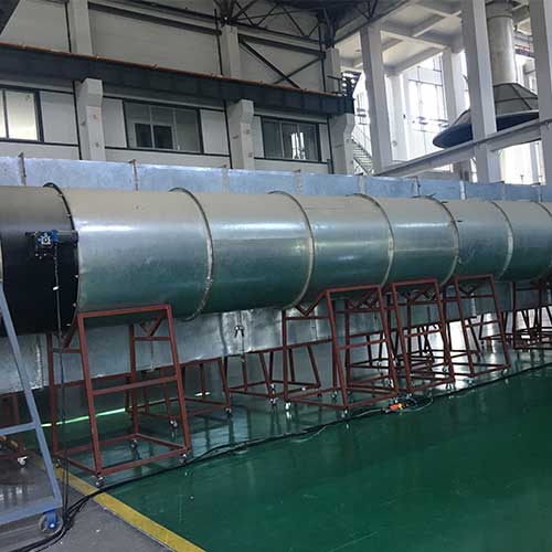
3.8.2 Pressure release pipeline: The part in the furnace is made of high temperature-resistant diameter 300mm, USU310S stainless steel tube, which can withstand high temperature of 1300 ℃, and has a manual valve on the upper part for air cooling. A welded pipe with a wall thickness of 5mm is used outside the furnace, and there are multiple water spray heads inside for water vapor cooling. The exhausted flue gas (the inlet temperature of the dust removal system) should not exceed 160°C.
3.8.3 Pressure release power: AC380, 15kw high-pressure fan with high temperature resistance.
3.8.4 Cooling method: adopt air-cooling cooling method. The cooling pipeline is about 3m, and the cooling effect is very good. See Figure 9
3.8.5 Furnace pressure control and data acquisition, the furnace pressure can ensure real-time control according to standard requirements and smoke exhaust system to form a control loop
3.9 Fire observation hole: There is a fire observation hole on the back side wall of the furnace body, which is used to observe the fire surface and flame of the test piece during the test. Necessary measures such as temperature collection.
3.10 Gas alarms: 2; used in gas chambers and test sites.
3.11 High temperature resistance sample test device of fire smoke exhaust fan:
3.11.1 The furnace body is designed to meet the replacement and installation of sample tests of different specifications, and realize the detection of the fire resistance performance system of the fire-fighting smoke exhaust fan.
3.11.2 Composition: Consists of collector, electric air volume control valve, fan aerodynamic performance test pipe (standardized air duct), fire exhaust fan, rear connecting pipe of fire exhaust fan, and vibrometer sensor of fire exhaust extension unit , measurement system composition of flow, pressure, temperature, time, and full efficiency;
3.11.3 Structure: the outlet and inlet of the pipeline are connected with the furnace, so as to form a heat flow cycle between the fire exhaust fan and the high temperature resistance test furnace; the front and rear connecting pipes of the fire exhaust fan are made of 5.0mm thick stainless steel plate . The size and shape of the standardized air duct meet the requirements of GB/T1236-2000.
3.11.4 All air ducts of fire-fighting smoke exhaust fans (axial flow, centrifugal) are connected by flanges; fans with standardized air duct sizes of N0.5, N0.8, and N0.12 are connected at the front and rear There are three sets of pipes. All contain current collector, electric air volume control valve, temperature measurement, pressure measurement, flow measurement, vibration meter, rectifier grid, reducing joint, air cap, etc. And fire smoke exhaust fan (axial flow, centrifugal) in the specified wind tunnel to measure the aerodynamic performance of the fan under high temperature conditions, including vibration meter, flow rate, pressure, temperature, time, full efficiency measurement sensor and detection system, etc., if these parameter tests cannot be shared according to the standard requirements. For the detection of other brands of fans, the test can be carried out by adding the corresponding accessories as mentioned above, and the optional part needs to be quoted separately.
3.12 Fire resistance test of ventilation duct:
3.12.1 Suitable for rectangular pipes A: width 1000mm, height 500mm; B: width 1000mm, height 250mm; round pipes: A: diameter 800mm, B: 630mm;
3.12.2 Pipeline A maintains a pressure difference of 300Pa, and pipeline B maintains an air flow rate of 3m/S;
3.12.3 Meet the requirements of GB/T17428-2009 standard.
3.13 Flue gas emission purification system: the exhaust gas treatment (purification) system of the refractory test furnace is not equipped, and exhaust gas discharge pipelines, cooling devices, exhaust gas induced draft fans, and the connecting pipelines between the induced draft fans and the dedusting system of the tenderee are provided, and the inlet temperature of the dedusting system shall not be adjusted. over 200°C.
3.14 Computer control system and data acquisition:
3.14.1 Use computers, modules and PIDs. Data acquisition and analysis software WINDOWS XP operation interface, global precision equipment development software LabView; including: main control interface, furnace temperature curve interface, pressure display, specimen temperature interface, with historical data storage, query and other functions, and can be converted into EXCEL documents save.
3.14.2 The test records (3 seconds/time) are stored by number and can be queried at any time; the printing effect of the test report can be viewed in real time, and it can be completed by simply clicking the buttons such as start, calculation and save, which is easy to use.
3.14.3 At the same time, the data retrieval function is added, which can load the previous experimental data for recalculation and form a report.
3.14.4 The system includes fire smoke exhaust fans (axial flow, centrifugal type) in the specified wind tunnel to test the aerodynamic performance of the fans under high temperature conditions, see GA 211-2009 High temperature resistance test methods for fire smoke exhaust fans and GB/ T 1236-2000 Standardized air ducts are used for performance testing of industrial ventilators.
3.14.5 Free software upgrade for life.
3.15 Instrument configuration:
3.15.1 1 set of main engine: the main test part includes: vertical refractory furnace, combustion control system, smoke exhaust system, furnace temperature data acquisition system, test component temperature acquisition system, smoke exhaust valve system, smoke exhaust fan fire resistance system detection , Smoke exhaust fan aerodynamic performance test system, control computer, special software for testing equipment;
3.15.2 A set of computer and color laser printer;
3.15.3 Three sets of fire-fighting smoke exhaust fan test devices.
 WhatsApp:
 Mobile Phone:
 Contact Now