The Fire Resistance Tester Comply with DIN 4102 and GB/T 8625-2005 "Test method of difficult-flammability for building materials"This standard applies to the determination of the flame retardancy of building materials.
1. Scope of application:
This standard specifies the test equipment for the flame retardancy test of building materials, the preparation of test pieces, the test operation, the judgment of the remaining length of the test piece after burning, the judgment conditions and the test report.
This standard applies to the determination of the flame retardancy of building materials.
2. Compliant standards:
Comply with DIN 4102 and GB/T 8625-2005 "Test method of difficult-flammability for building materials"
3. Test device:
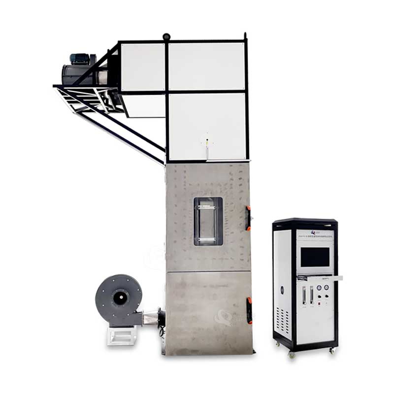
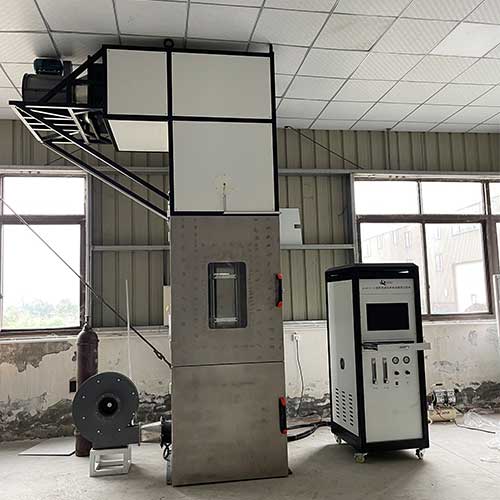
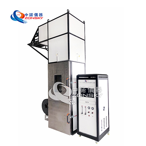
The test device of this method mainly includes two parts: burning shaft furnace and test equipment.
3.1 burning shaft furnace
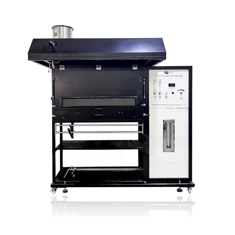
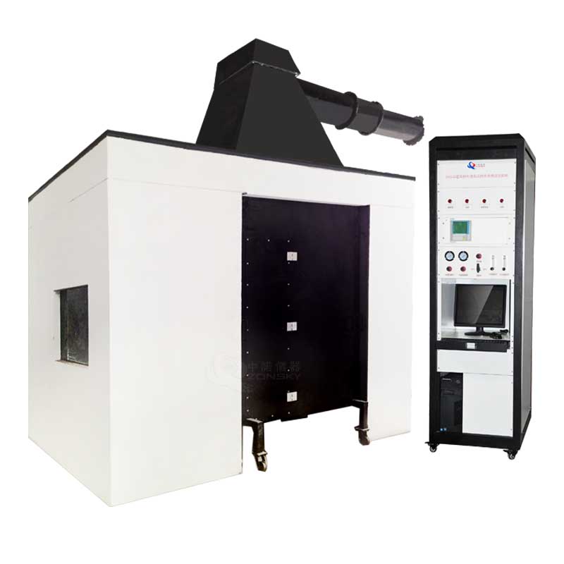
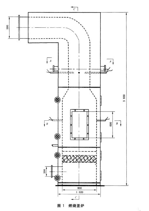
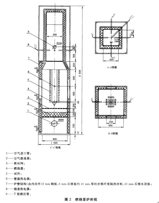
The burning shaft furnace is mainly composed of burning chamber, burner, specimen support, air steady flow layer and flue. Its overall dimensions are 1020mmX1020mmX3930mm (see Figure 1 and Figure 2)
3.1.1 burning chamber
The burning chamber is composed of a furnace wall and a furnace door, and its inner space size is 800mmX800mmX2000mm. The furnace wall is an insulating interlayer structure, and its structural form (see Figure 2). The furnace door is divided into upper and lower doors, which are respectively connected to the furnace body by hinges, and its structure is similar to that of the furnace wall. The two doors are closed with the furnace body by means of hand wheels and fixed screws. There are observation windows on the upper furnace door and the rear wall of the burning chamber.
3.1.2 Burner
The burner (see Figure 3) is placed horizontally in the center of the burning chamber, 1000mm from the bottom of the furnace.
3.1.3 Specimen support
The test piece support is a rectangular frame with a height of 1000mm. The four sides of the frame are provided with screw rods to adjust the installation distance of the test piece. The frame is made of angle steel (see Figure 4)
3.1.4 Air stabilization layer
The air stabilization layer is a square frame made of angle steel, which is set under the burner. Steel wire mesh is laid on the bottom of the square frame, and multiple layers of glass fiber felt are laid on it.
3.1.5 Flue
The flue of the burning shaft furnace is a square channel with a cross-sectional area of 500mmX500 and is located on the top of the furnace. The lower part communicates with the burning chamber, and the upper part connects with the external chimney.
3.1.6 Gas supply
In order to form a uniform airflow in the burning chamber, air is input at a constant rate and temperature through a Φ200mm pipe at the lower part of the furnace body.
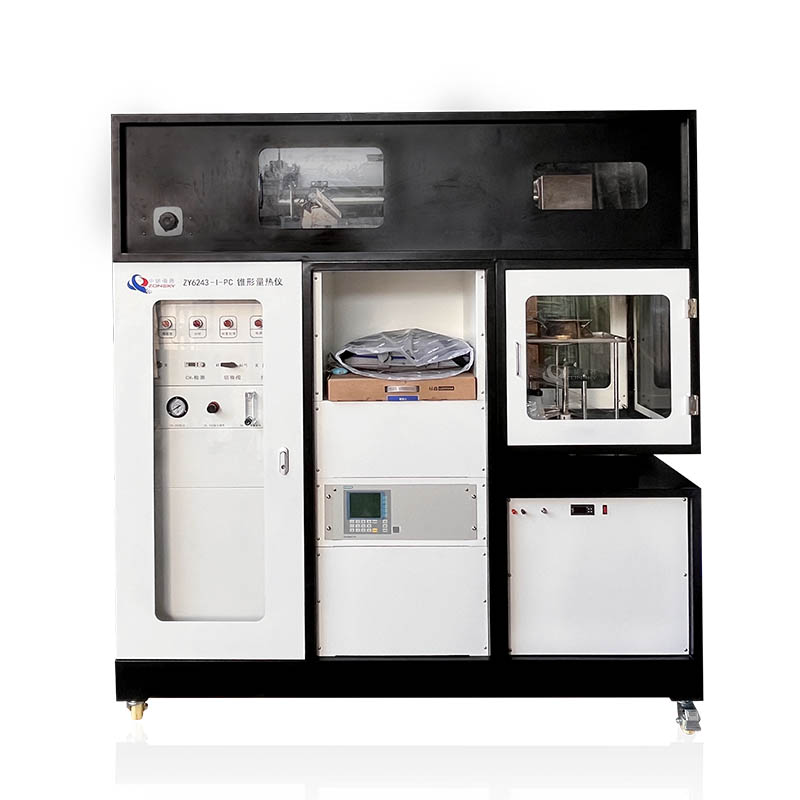
3.2 Test equipment
The test equipment of the burning shaft furnace includes flowmeter, thermocouple, temperature recorder, temperature display instrument and furnace pressure test instrument, etc.
3.2.1 Flow meter
For the measurement of methane gas and compressed air flow, a flow meter with a precision level of 2.5 and a range of (0.25~2.5) m³/h is selected.
3.2.2 Thermocouples
Flue gas temperature and furnace wall humidity are measured by nickel-chromium-nickel-silicon galvanic couples with precision grade II, wire diameter of 0.5mm, and outer diameter of not more than 3mm. See Figure 2 for the installation location.
3.2.3 Temperature recorder and display instrument
The temperature measurement is displayed and recorded by a microcomputer, and its test accuracy is 1°C; it can also use an electronic potentiometer with a precision of 0.5 that can be continuously recorded with a thermocouple or other suitable continuous recording instruments.
3.3 Furnace pressure
At the flue part 2700mm from the bottom of the furnace, a T-shaped furnace pressure test tube is installed at a distance of 100mm from the flue wall. The inner diameter of the T-shaped tube is 10mm, and the head width is 100mm. A differential pressure transmitter with a precision of 0.5 and a computer or other The recorder is connected for continuous monitoring.
3.4 Calibration tests of components in the burning shaft furnace
3.4.1 Uniformity test of thermal load
In order to ensure the uniformity of the thermal load on the specimen during the test, place four 1000mmX3mm stainless steel plates on the specimen rack, and securely set a nickel-chromium-nickel-silicon For thermocouples, conduct the test according to the operating procedures specified in Chapter 5. After the test is carried out for 10 minutes, the average temperature measured by the four thermocouples on the above stainless steel plate should meet 540°C±15°C, otherwise, the device should be debugged , the test must be performed every 3 months.
3.4.2 Air uniformity test
Under the gas supply condition with the furnace door closed under the burning shaft furnace, take 5 points on the steel wire net in the air steady flow layer (see Figure 5), and at a distance of 50mm from the net, use a hot-ball micro anemometer or Other anemometers with the same accuracy, measure the wind speed at each point. The average value of the wind speed measured at the 5 speed measuring points is converted into the gas flow, and it should meet the (10±1) ㎡ min gas supply specified by the shaft furnace. This test must be carried out once every six months.
3.4.3 Inspection of flue gas temperature thermocouple
In order to ensure the accuracy of flue gas temperature measurement, the flue gas temperature thermocouple should be inspected at least once a month, the smoke should be removed, and the thermocouple should be corrected to the specified position if it is displaced or deformed.
 WhatsApp:
 Mobile Phone:
 Contact Now